An SLS surface is not a defect to be eliminated as a matter of course: it is the predictable result of a powder-bed process and can already be adequate for many functional components in the raw state. This guide to SLS surface roughness clarifies which parameters to evaluate, which values to expect and when an additional finish brings a real technical benefit.
For anyone designing a functional prototype, a small run or a component for end use, the right question is not "how smooth is an SLS print?". It is: what roughness does that function need, on that geometry, with that material and that post-processing?
What determines the roughness of an SLS surface
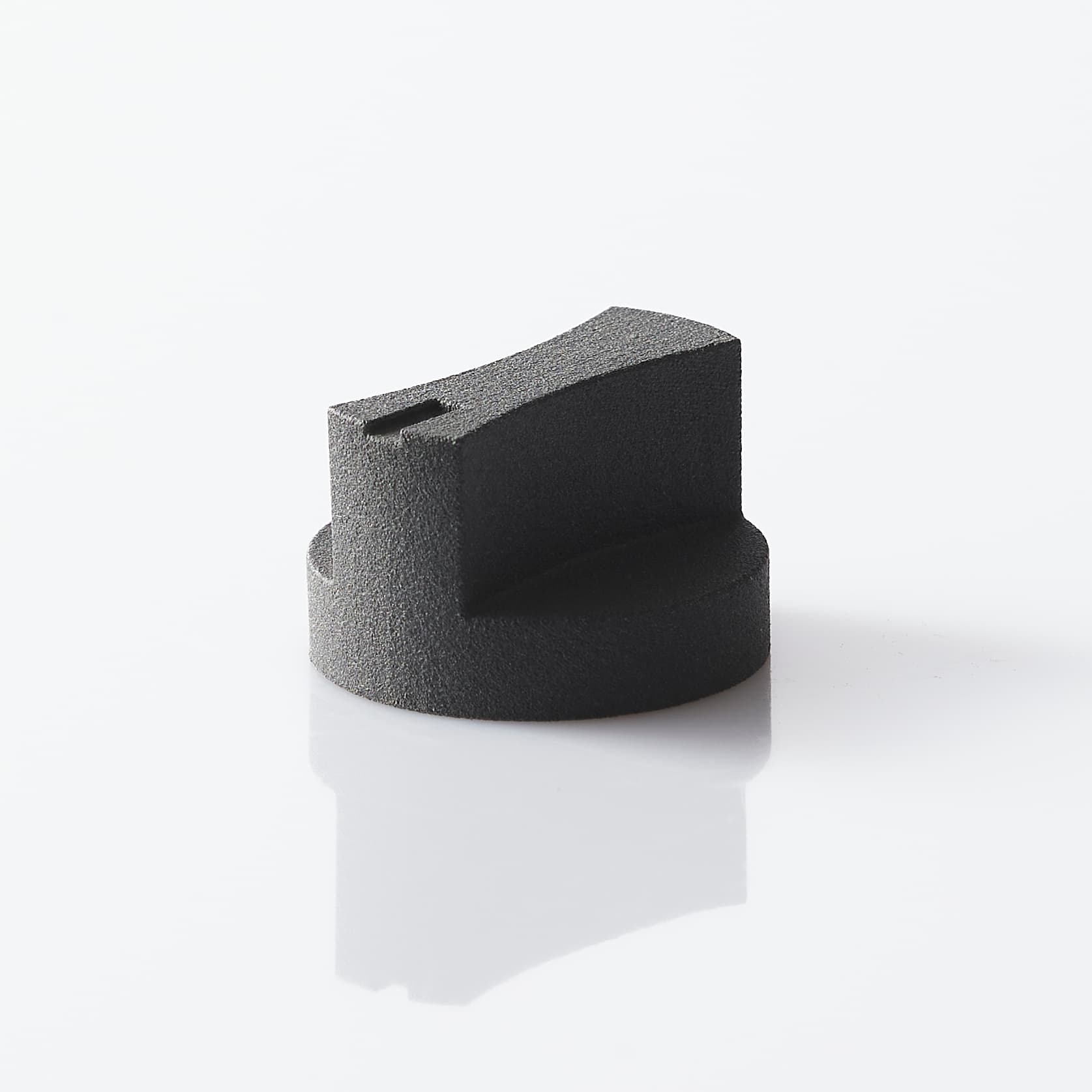
In selective laser sintering, the laser locally fuses successive layers of polymer powder. In the typical case of PA12, some of the particles remain partially visible on the outer skin of the part. The result is a matt finish, slightly grainy to the touch, very different from the surface of a milled part or one injection-moulded in a polished tool.
The actual roughness does not depend only on the machine. Layer thickness, particle size distribution of the powder, exposure parameters, bed temperature, scanning strategy and cooling management all play a part. Geometry matters too: inclined surfaces, deep cavities, thin edges and very small details can look different from flat, vertical walls.
Orientation in the chamber is one of the most relevant factors. The same part can have more uniform side faces and surfaces facing up or down with a more noticeable texture. There is therefore no single roughness value valid for the whole component: a technical specification must state the functional area, the measurement direction and the required finish.
Ra, Rz and other parameters: how to read a specification
Roughness is often summarised with the Ra parameter, i.e. the mean deviation of the profile from the mean line. It is useful because it is easy to compare, but it does not fully describe the topography of an SLS surface. Two surfaces with a similar Ra can have very different peaks, valleys and profile distributions.
Rz, which considers the characteristic height between peaks and valleys of the profile, can be more indicative when localised asperities are present. For surfaces with a sealing, sliding or mating function, it can also be useful to define the measurement method, the sampling length and the reference standard, now generally the ISO 21920 series.
As an order of magnitude, a PA12 SLS part that has been depowdered but not finished can show Ra values in the region of about 8–15 µm. The figure should be treated as a process reference, not a universal guarantee: material, orientation, part area and production batch can shift the result. If a contractual requirement calls for a maximum Ra value, it must be agreed for the specific surface and validated with a sample or test piece.
Roughness, moreover, does not coincide with dimensional accuracy. A component can meet the main dimensions and have a surface unsuitable for a sealing seat. Conversely, a slightly rough surface can be perfectly suited to a technical shell, a mount, an assembly jig or an ergonomic component.
SLS surface roughness by part function
The choice of finish must start from the application. For covers, housings, brackets, mounts and non-aesthetic structural components, the standard SLS finish is often the most efficient solution. It keeps time and cost under control, preserves details and complex geometries well and offers the matt technical look typical of PA12.
For parts that are handled frequently, such as grips, portable devices, test instruments or design components, controlled smoothing or a chemical-mechanical finish can reduce the perception of grain and improve cleanability and comfort. The trade-off must be considered, however: the more the surface is evened out, the greater the effect can be on micro-details, sharp edges, raised text and local tolerances.
In pneumatic ducts or fluid passages, roughness affects pressure drops, residue build-up and cleanability. SLS printing allows internal channels that are hard to obtain with traditional machining, but the finish of internal cavities is less controllable than that of accessible faces. In these cases it is useful to design adequate diameters, provide access openings for depowdering and assess whether the flow requirement calls for an additional technology or process.
For seal seats, threads, sliding fits and reference surfaces, it is not advisable to rely automatically on the raw surface. It can be more effective to print with a machining allowance and carry out selective machining, fit bushes or use standard elements. It is a more rational solution than asking the print to perform a function for which the process is not optimised.
Post-processing finishes: what they really change
Thorough depowdering is the first necessary step and should not be confused with an aesthetic finish. It removes unsintered powder and leaves the surface clean and usable, without substantially transforming its texture.
Tumbling or mechanical smoothing reduces the most exposed asperities and makes the feel more uniform. It suits many external parts, but it can round the edges and reaches cavities, undercuts and internal channels only to a limited extent. The result is influenced by the mass of the part, its geometric fragility and the position of the details.
Dyeing PA12 is a frequent choice for small-run components. Technical black, for example, makes the appearance more uniform and reduces the visibility of minor surface marks, but it does not eliminate roughness. This is an important distinction: colour changes aesthetic perception, but it does not replace a finish when the requirement is metrological or functional.
Specific smoothing treatments can lower roughness significantly and improve cleanability, especially on external surfaces. They do, however, require a prior assessment of geometry, material and tolerances. Thin walls, tight fits and very fine lettering deserve particular attention, because post-processing always alters the skin of the component, even if only slightly.
Designing for controlled roughness
The most useful specification is not "smooth surface", but a verifiable request. For example: bearing area with a smoothed finish, a maximum Ra agreed on a defined face, a seal seat to be machined after printing, or an internal channel sized to maintain the required flow even with an unsmoothed wall.
It is worth identifying the critical surfaces on the CAD and separating them from purely aesthetic ones. In this way the technician can define the most suitable orientation, verify the feasibility of post-processing and propose any changes before production. Generic indications delivered after the quote often produce additional costs or results that cannot be compared.
Pay attention to lettering and markings too. Raised or recessed text must have sufficient depth and width to remain legible after depowdering and finishing. When durable codes, batch references, logos or technical identifiers are needed, laser engraving carried out after printing can offer a sharper, more repeatable marking than details that are too small modelled directly on the rough surface.
From sample to small run
If the surface is a decisive requirement, the safest route is to validate a representative sample. It is not enough to verify the material: finish, colour, orientation, functional geometries and measurement method must be tested. This step is particularly useful for pre-series, non-implantable medical devices, production equipment, laboratory components and products intended for sale.
Repeatability comes from a complete specification and a controlled process. A service provider that handles file checking, printing and post-processing in-house can keep a single point of contact between the initial geometry and the finished part. Doppialinea tackles this assessment already at the technical stage, to avoid treating the finish as an add-on disconnected from the function of the component.
When roughness has an impact on sealing, friction, cleanability or the perception of the product, stating it from the moment the CAD is sent makes it possible to choose the most effective solution: raw SLS surface where it is sufficient, localised finishing where it adds value, or subsequent machining where a tighter tolerance is needed. This is how 3D printing becomes a controlled production choice, not a compromise to be accepted after delivery.