A sensor mount that vibrates, a gripper that flexes more than expected or a housing that interferes with a wiring harness can halt weeks of testing. The most useful examples of robotics components are therefore not simply 3D-printed objects: they are parts designed to solve real constraints of load, movement, envelope, maintenance and repeatability.
In the development of automated cells, mobile robots, end-effectors and vision systems, additive manufacturing makes it possible to go from CAD file to functional test in a short time. The benefit is not only speed. It allows a geometry to be iterated, functions that were previously separate to be integrated, and small runs to be produced without waiting for tooling or moulds. To obtain a usable component, however, material, technology and design must be chosen together.
Examples of robotics components and their function
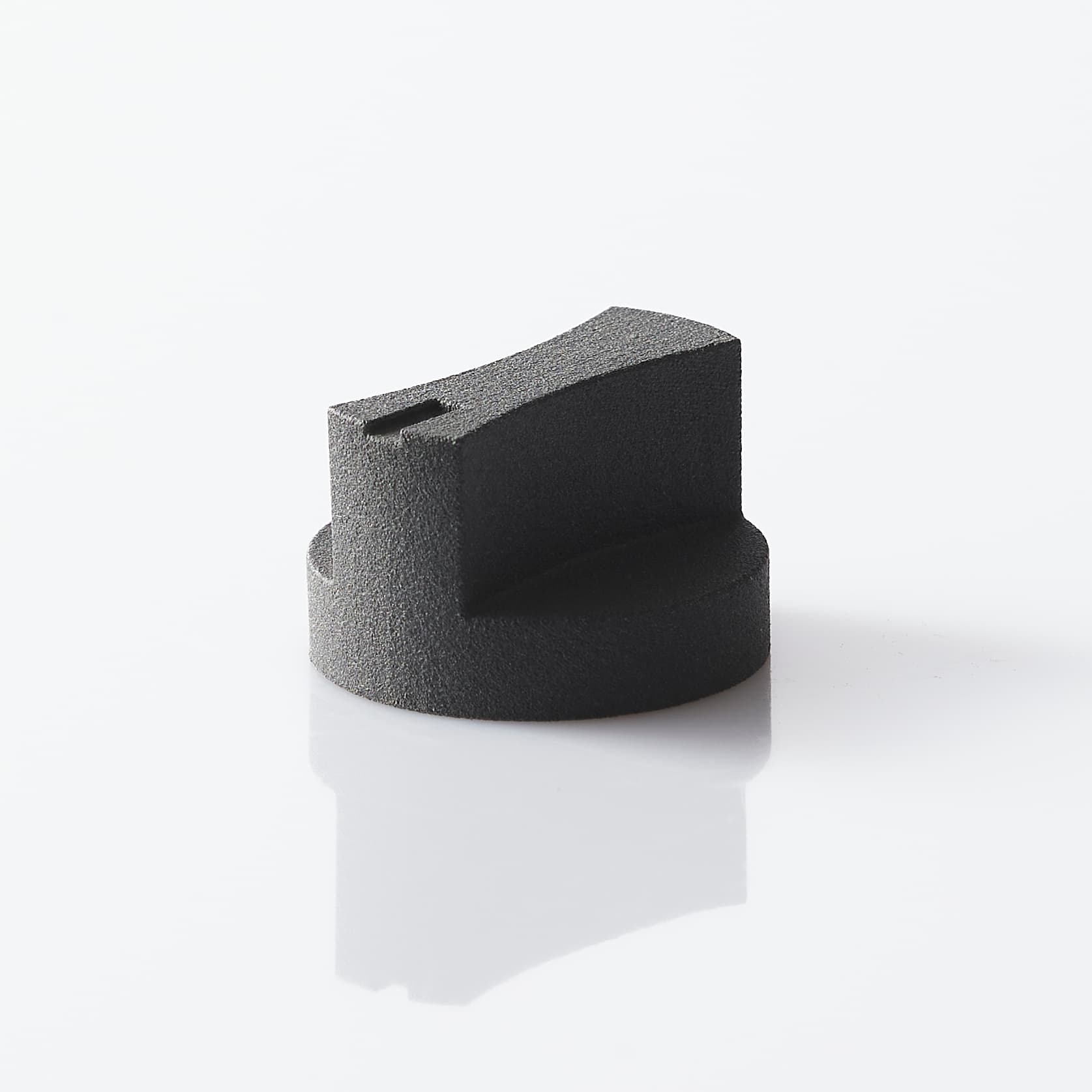
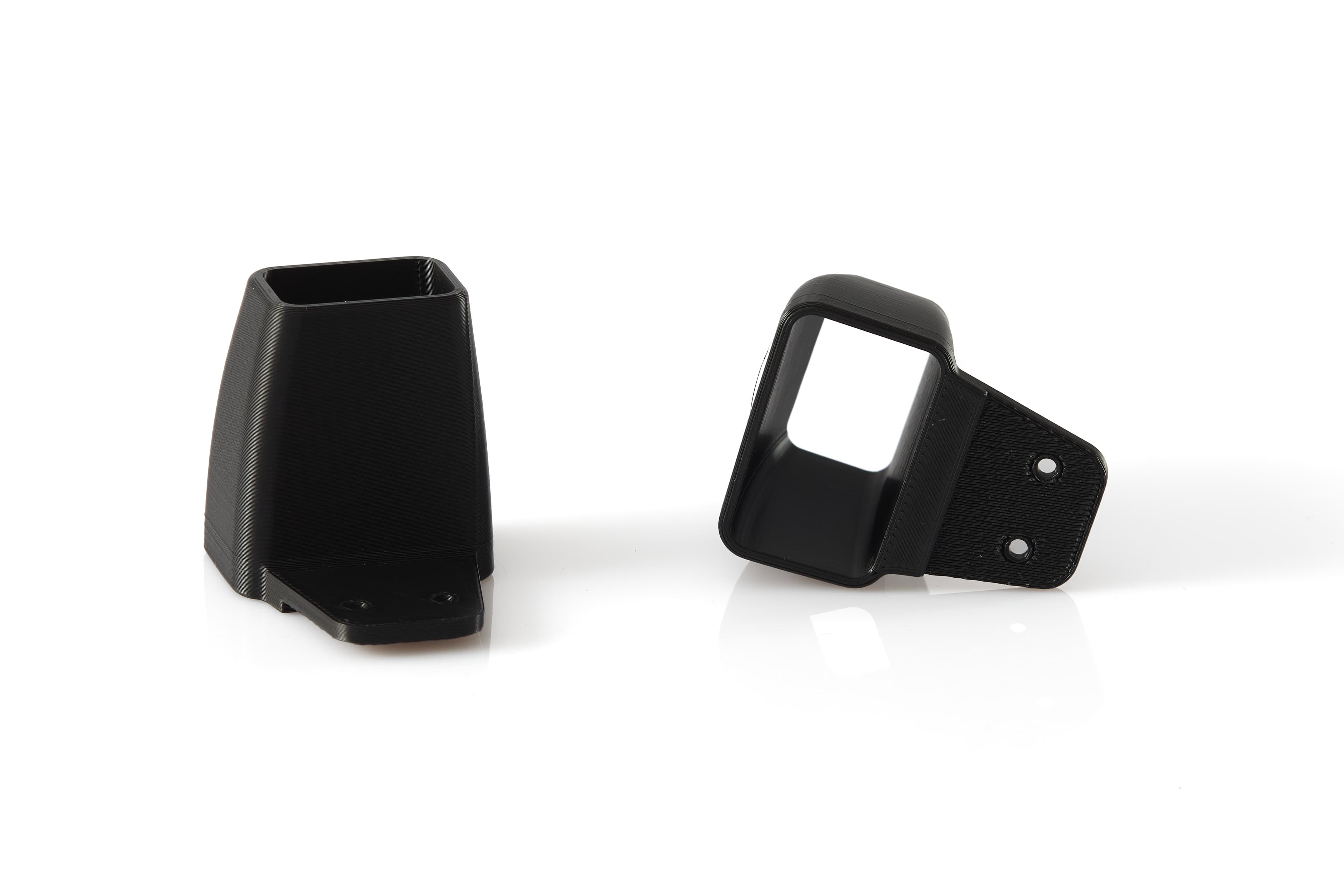
A first group comprises non-load-bearing or semi-structural components: fixing brackets, camera mounts, sensor bases, spacers, covers and cable guides. They are apparently secondary elements, but they affect the accuracy of the system. A bracket for a vision camera, for example, must maintain optical alignment under vibration and must not deform when the robot accelerates.
A second group concerns end-effectors. Gripper fingers, shaped jaws, suction cups supported by adapters, centring guides, gripping jigs and interface plates can be customised to the shape of the product being handled. Here 3D printing is particularly effective because it lets you adapt the contact to the part, lighten the moving assembly and quickly change the grip when format, batch or packaging changes.
Mobile robots and autonomous platforms include electronics housings, battery enclosures, lidar mounts, connector guards, bumpers and antenna mounts. In these cases the part has to cope with impacts, dust, wiring and the need for inspection. A cover that looks clean but is hard to remove can add more maintenance time than it saves during assembly.
A fourth area is production equipment: assembly jigs, check gauges, nests, insertion guides and poka-yoke devices. These are not components installed on the robot, but they make the construction and testing of the system more reliable. The ability to integrate references, bush seats and engraved indications reduces operator errors and makes the process more repeatable.
The right question is not just which part to print
Before selecting a technology, the function of the part must be defined. A protective housing, a bracket subject to bending and a jaw in contact with a delicate surface can have similar shapes but require different things. The choice starts from four checks: loads and direction of stresses, operating environment, required tolerances and the number of parts expected.
For a structural part it is worth estimating static load, dynamic peaks and the number of cycles. In robotic systems acceleration can generate significant forces even on small masses. If the component supports a sensor or a gripper, the calculation must also consider the lever arm, vibration and the effect of the fixings. When high stiffness is needed, it is often preferable to increase ribs and sections in the right places rather than making the whole wall uniformly thicker.
The working environment changes the choice. A component near lubricants, solvents, heat sources or frequent washing needs specific compatibility checks. Likewise, a part exposed to UV light or used outdoors cannot be chosen on surface appearance alone. The electrical requirement matters: some housings may need insulation, cable management and geometries that avoid chafing or pinch points.
Materials and technologies for functional parts
PA12 produced with SLS technology is often specified for mounts, covers, brackets, small runs and components with complex geometries. It offers a good balance of mechanical strength, stability and design freedom. The absence of print supports makes it possible to create channels, interlocks and organic shapes with fewer constraints than many traditional processes. Functional tolerances must still be taken into account, with machining or dedicated seats planned where the fit is critical.
TPU is suited to soft fingers, impact guards, gripping elements and flexible cable guides. Its usefulness does not come only from flexibility: it can increase friction on the handled product and reduce the risk of marks or damage. The trade-off is lower accuracy in very thin geometries and an elastic response that must be assessed against load, temperature and number of cycles.
MSLA resins are an effective choice for highly detailed prototypes, compact covers, components with accurate surfaces and fit checks. Engineering formulations exist for specific requirements, but the behaviour of the resin must be assessed for the use case, especially if the component is subject to repeated impact or prolonged loads. An accurate part is not automatically a part suited to working for thousands of cycles.
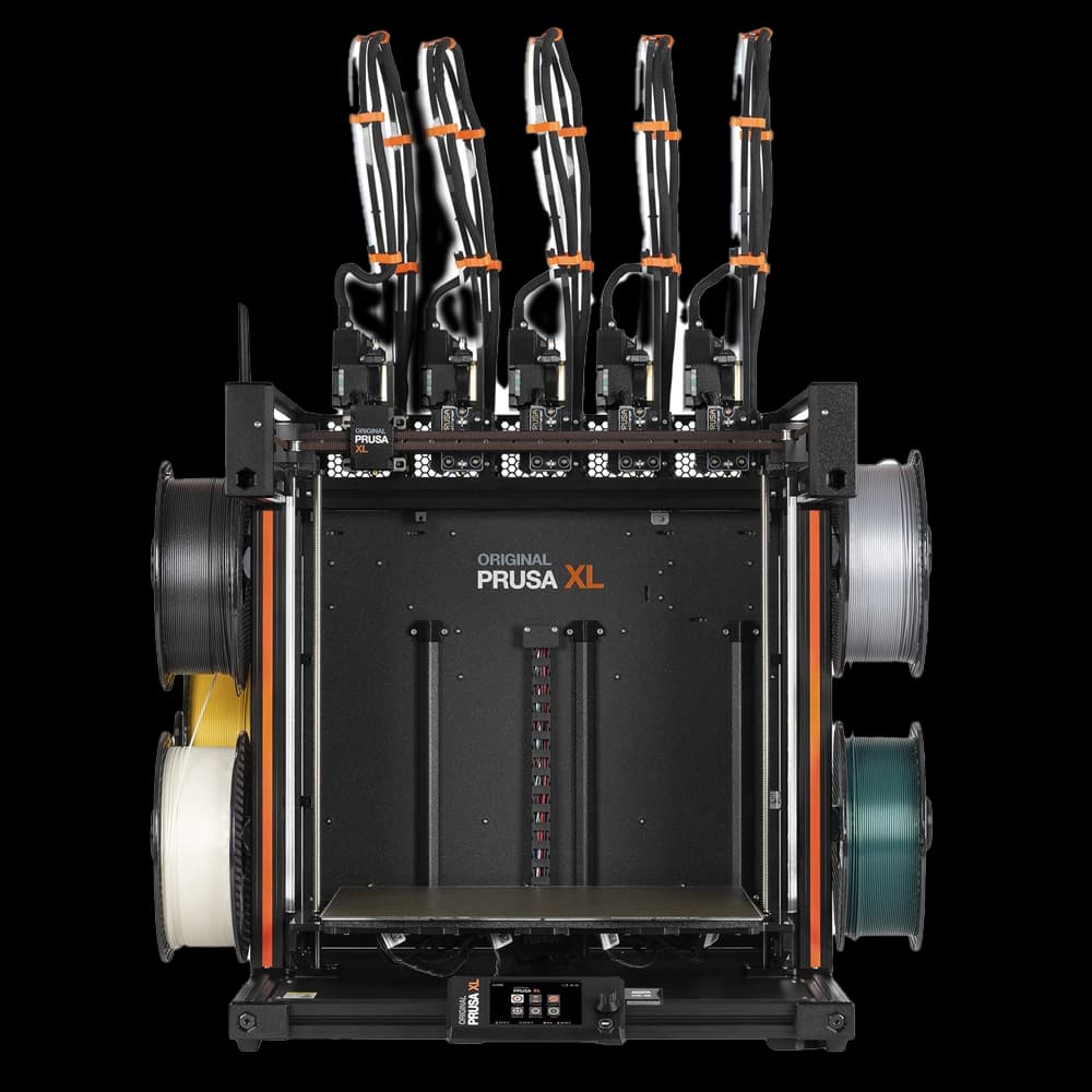
FDM technology can be a practical solution for jigs, test fixtures, guards and dimensional prototypes, particularly when size, time and cost are priorities. The print direction must, however, be defined with respect to the stresses. In layered parts, orientation affects strength and the quality of functional surfaces.
Designing geometries that assemble first time
In robotic components, the geometry must also be designed for assembly. Holes threaded directly into the plastic may be fine for a prototype or for limited interventions, but at points subject to repeated assembly threaded inserts, bushes or integrated metal elements are often preferable. The choice depends on the tightening torque, the number of cycles and how critical the connection is.
Thin walls require attention. A housing can be lightweight, but it must keep its shape and flatness near screws, clips and connectors. Ribs, fillet radii and localised reinforcements help distribute stresses. Sharp corners and abrupt changes of section, on the other hand, concentrate stress and increase the risk of breakage.
For fits, it is useful to distinguish between assembly clearance, interference and precision reference. A press fit can be effective for closing a cover, but it is not the ideal choice if the part has to be opened every day. For sensors, guides and interface plates, geometric references must be placed close to the critical function, not left to depend on uncontrolled external surfaces.
Wiring also deserves design attention. Providing adequate radii, fixing points, inspection windows and space for connectors reduces problems during installation. A CAD file that is correct from an aesthetic standpoint can become unusable if it does not consider access to a screw or the travel needed to pull out a connector.
From prototype to small run without losing control
The first part serves to verify more than a dimension. It must be tested on the real robot, with actual wiring, fasteners, sensors and movement cycles. This is where interference, noise, flexing and assembly difficulties emerge. Documenting this evidence turns a quick fix into a traceable design revision.
When the component moves into pre-series, repeatability, identification and finish become central. Dyeing can unify the appearance of a batch and make the component more consistent with the final product. Laser engraving of codes, assembly references, revision and serial numbers simplifies traceability and maintenance, especially on equipment or components destined for several installations.
Doppialinea works at this stage from file to finished part with technical checking, in-house production and post-processing options, so as to assess not only printability but also the behaviour of the part in its real assembly. For a technical department, having a single point of contact reduces handovers between quotation, revision and production.
3D printing does not always replace CNC machining, sheet metal or moulding. If volumes rise significantly, if extremely tight tolerances are required or if the component is subject to high, continuous loads, a hybrid or traditional process may be more suitable. The value of additive lies in selecting it where it brings a measurable advantage: development speed, geometric complexity, customisation or limited production.
To turn an idea into a reliable part, the starting point is simple: design each component around its real function, not around the mere possibility of printing it. A good mount, a well-sized gripper or a clearly designed jig makes the whole robotic system work better.