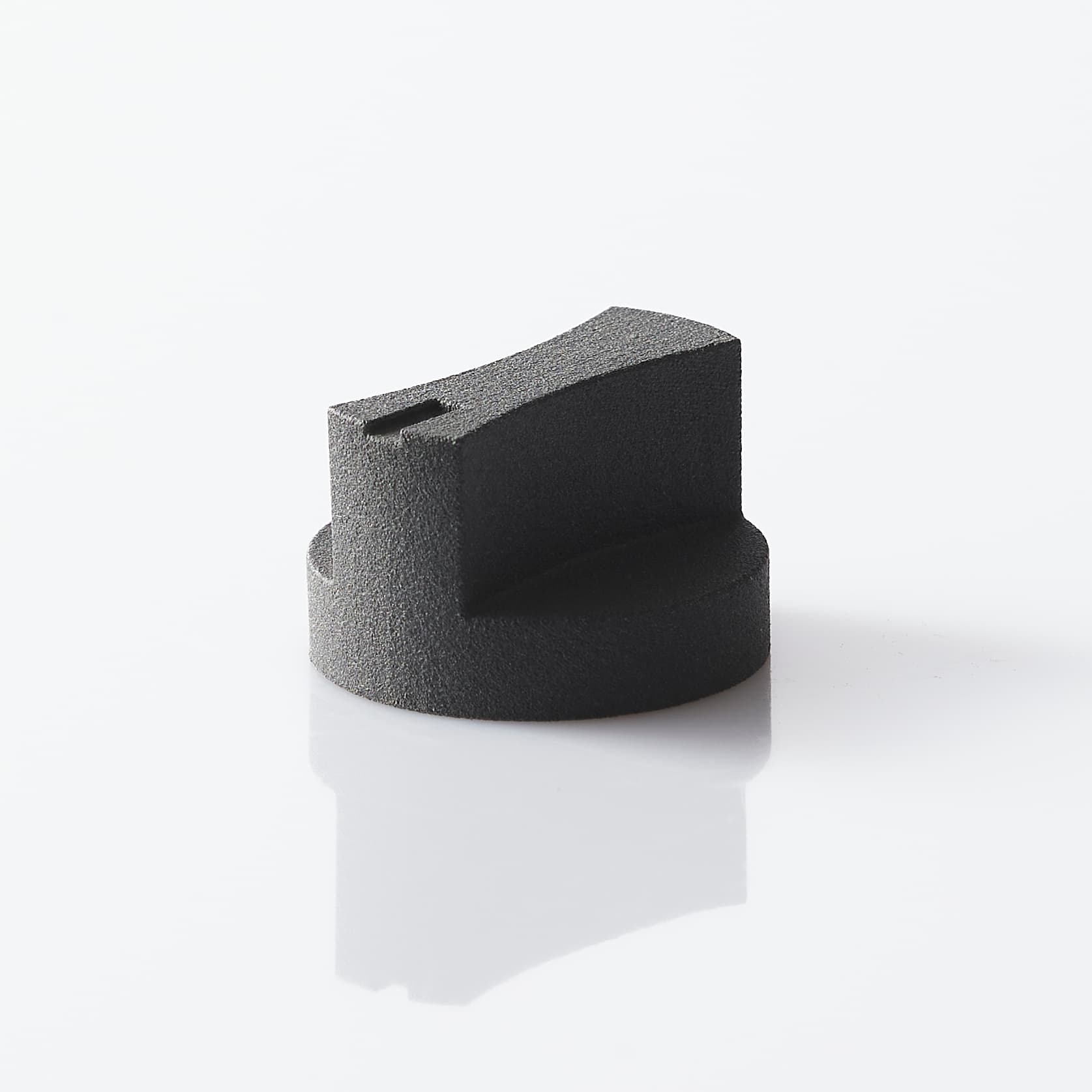
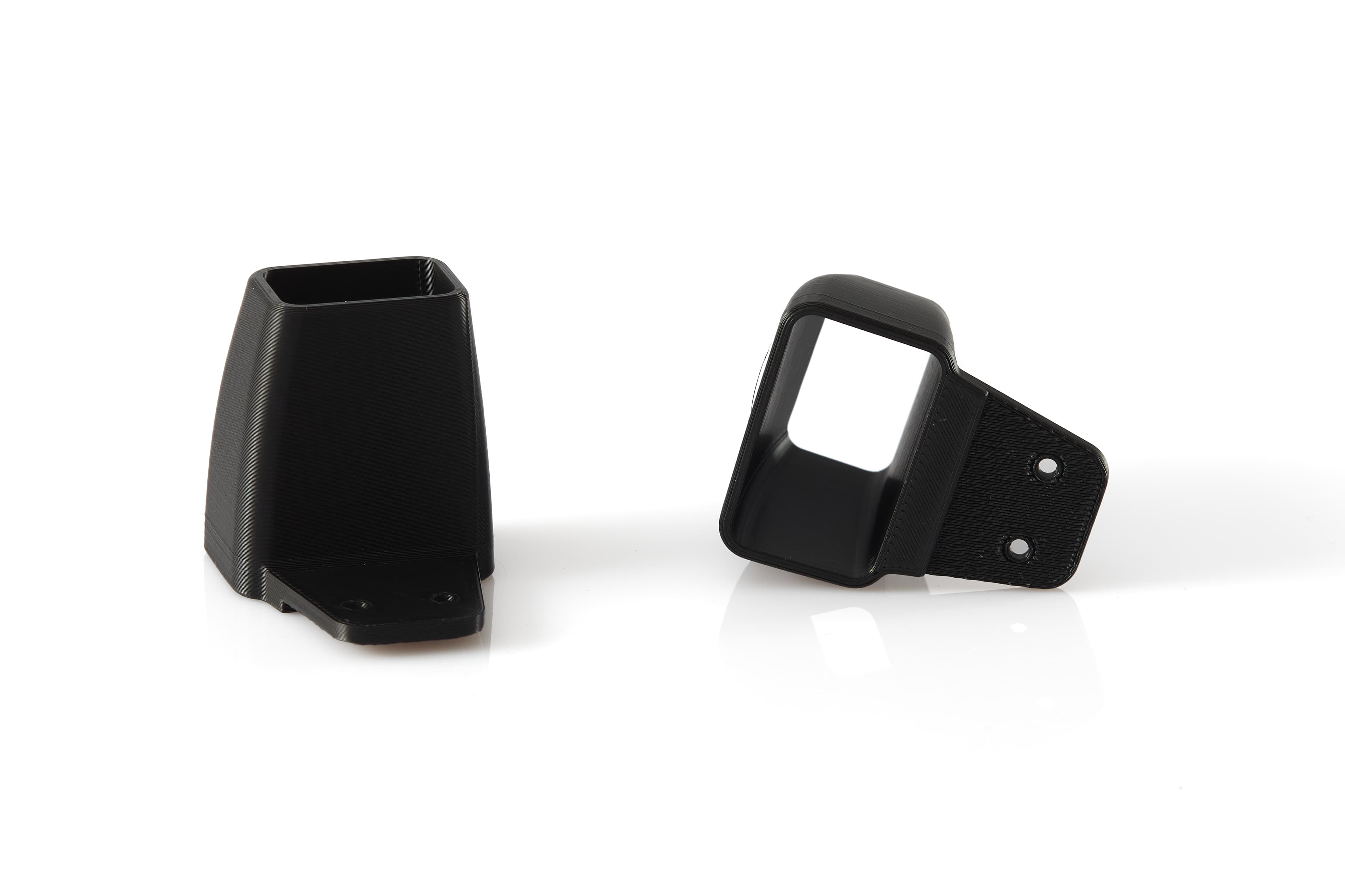
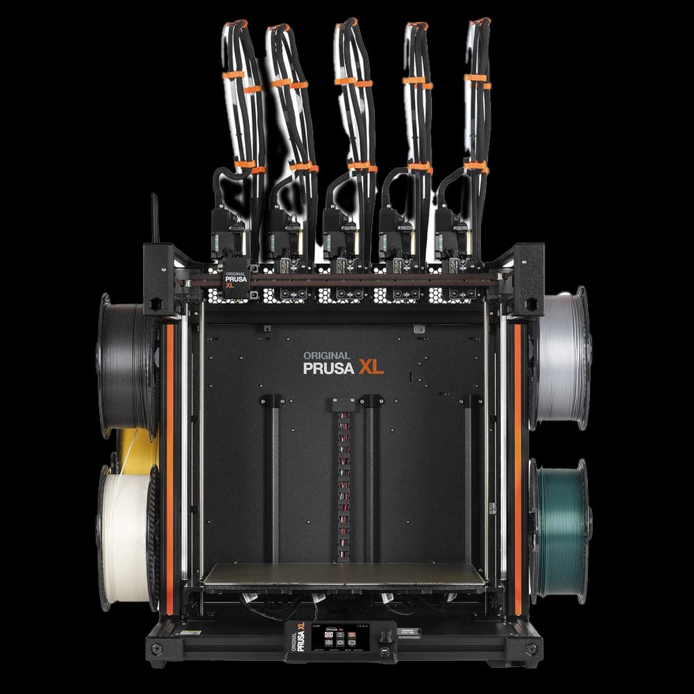
In selective laser sintering, understanding how to optimise the orientation of SLS parts means managing more variables than a simple placement in the build volume would suggest. There are no supports to remove as in FDM or stereolithography, but orientation affects dimensional accuracy, thermal behaviour, surface roughness, mechanical strength and accessibility for depowdering and finishing.
For an aesthetic prototype, a sub-optimal choice may be acceptable. For a small functional run, a component with mating features, thin walls or sealing requirements can suffer repeated deviations and avoidable post-processing costs. The goal is not to find a universally correct orientation: it is to define the one most consistent with the component's function, geometry, material and tolerances.
SLS part orientation: what really changes
SLS technology builds the part layer by layer by selectively fusing polymer powder, often PA12 or TPU, inside a thermally controlled bed. The unsintered powder supports the surfaces during the build, which makes complex geometries, undercuts and internal channels possible without dedicated support structures.
This freedom does not, however, remove the effects of the layered process. Surfaces inclined to the XY plane show steps that are more or less visible depending on the angle and the layer thickness. Faces pointing up, down or along the lateral axes can show noticeable differences in texture. In addition, the thermal cycle inside the chamber and the cooling of the nested build can affect local deformation and dimensional stability.
In practice, SLS orientation should not be chosen simply to "fit" the part in the chamber. It should be decided starting from the critical surfaces and the expected behaviour of the finished component.
Start from function, dimensions and critical surfaces
The first step is to identify what the part has to do, not just how it should look. A bracket with fixing holes, a housing with a locating face, an internal duct and an aesthetic shell call for different priorities.
Define the functional dimensions first: bearing seats, centre distances, threaded holes to be finished, mating faces, snap-fits, sliding surfaces. These features must be assessed against the build axes and the required tolerances. If a cylindrical seat needs high precision, it may be useful to plan a machining allowance or a subsequent machining operation, rather than relying exclusively on print orientation.
For aesthetic surfaces, decide which sides will be visible in the assembly. A uniform SLS texture is often appreciated in technical components, but it may not be enough for an element intended for product design. In that case the orientation should be coordinated with dyeing, bead blasting, painting or other planned finishes.
An effective working approach is to assign a priority to each area of the model: functional, aesthetic or secondary. When two requirements conflict, the declared priority avoids arbitrary decisions when the job is prepared.
Managing the layer effect and surface finish
Horizontal and vertical surfaces do not react in the same way to layered construction. Vertical walls tend to preserve profiles and edges well along the Z direction, while inclined surfaces can make the stair-step effect more noticeable. This matters on large aesthetic faces, fillets, raised logos and mating surfaces.
There is no absolute rule such as "always put the best face upwards". The finish also depends on the machine, material, layer thickness, position in the chamber and post-processing. There is, however, a design rule: avoid placing a large critical surface at a random inclination when it can be oriented to reduce the steps or make their pattern less visible in actual use.
For example, a front cover can be oriented so that the visible face has a more uniform texture and any layer lines follow a less conspicuous direction. A mechanical component, by contrast, may prioritise bearing faces and holes, accepting an aesthetic variation on unexposed surfaces.
Mechanical strength and load direction
SLS parts in PA12 have high and relatively uniform mechanical properties compared with many extrusion processes. Even so, layer-by-layer construction can introduce slight anisotropy. When the component works under tension, bending or fatigue, the load direction deserves attention.
For a lever, an elastic tab or a stressed support, it is worth analysing where the stresses concentrate and how the load-bearing sections are distributed. Orientation does not replace correct sizing, adequate fillet radii or the choice of material, but it contributes to repeatable behaviour.
In TPU the assessment changes further. A flexible geometry can be sensitive not only to load direction but also to deformation during depowdering and to the presence of thin walls. In these cases it is preferable to share the real use case: required hardness, flex cycles, compression, temperature and contact with other components.
Depowdering: the often underestimated constraint
Trapped powder is one of the most common problems in models designed without considering the process. Channels, cavities, closed volumes and internal lattices must allow the unsintered powder to escape in a controlled way. Orientation can help with this, but it cannot make up for missing or undersized openings.
A hollow container, for example, needs drain holes positioned to suit the cleaning flow. If the part is then rotated in the chamber, gravity is not the only factor, but the layout of the passages remains decisive for access by tools and compressed air.
For fluid ducts, manifolds and lattice structures, minimum diameters, tight bends, blind branches and possible stagnation points must be checked. The requirement is not only to obtain the channel in the print, but to deliver a component that is actually clean and usable. If a reliable seal is needed, it is also worth considering any subsequent treatments compatible with the intended use.
Deformation and thermal control in the chamber
Large, flat or very asymmetric geometries can accumulate thermal stresses during sintering and cooling. Thin plates, open frames, C-shaped components and extended walls are typical cases. Rotating the part can reduce some effects, but it does not correct an inherently unstable geometry.
In these situations several levers come into play: orientation, distribution within the nest, thicknesses, ribs, fillets and dimensional compensation. Sometimes the best solution is to split the component and provide an assembly system. In other cases it is better to locally increase a section or turn a continuous wall into a stiffened structure.
The choice depends on the priority constraint. If weight is critical, a rib may be preferable to a general increase in thickness. If the flatness of a bearing face matters, it may be more effective to plan machining after printing. Designing for SLS means considering the whole process, not isolating the moment of laser fusion.
How to define a production orientation
An effective technical workflow starts from the native CAD or from a correctly exported file. The STEP format allows a more complete check of the geometry, while a well-tessellated STL is suitable for print preparation. Before quoting or starting production, check units of measurement, minimum walls, open bodies, interferences and details below the useful resolution.
Next, classify the component by its use: visual prototype, assembly test, functional part, pre-series or finished component. This information guides decisions on orientation, material and finish far more than a generic indication such as "high quality".
For a functional part, indicate in the file or in the request the critical dimensions, the surfaces that must not show obvious layer marks, the expected loads and the areas that will receive inserts, threads or machining. For a series, also specify quantity, expected repeatability and the checks required. The service provider can then choose a consistent nesting instead of treating each part as an isolated model.
Doppialinea approaches this phase as a manufacturability check: from file to finished part, orientation is a decision integrated with material, post-processing and delivery requirements.
Mistakes that increase time and cost
The first mistake is requesting a specific orientation without stating the reason. Saying "print vertically" can be useful, but only if it is linked to an aesthetic face, a functional plane or a depowdering requirement. In the absence of a technical constraint, the manufacturer has to choose the most efficient solution for the job.
The second is treating all holes as equal. Clearance holes, precision seats, threads and ducts require different criteria. A printed hole may be adequate for a screw with clearance, while a toleranced seat may require calibration, a machining allowance or finishing.
The third is ignoring the relationship between orientation and post-processing. A part that will be painted can tolerate a different initial texture from a part left raw. Laser marking, on the other hand, requires an accessible surface and a sufficiently well-defined usable area. Anticipating these needs avoids rework and delays.
The right choice of orientation is not seen only in the file positioned in the chamber. It is measured at the moment the component comes out clean, meets the important dimensions, receives the planned finish and works at first assembly.