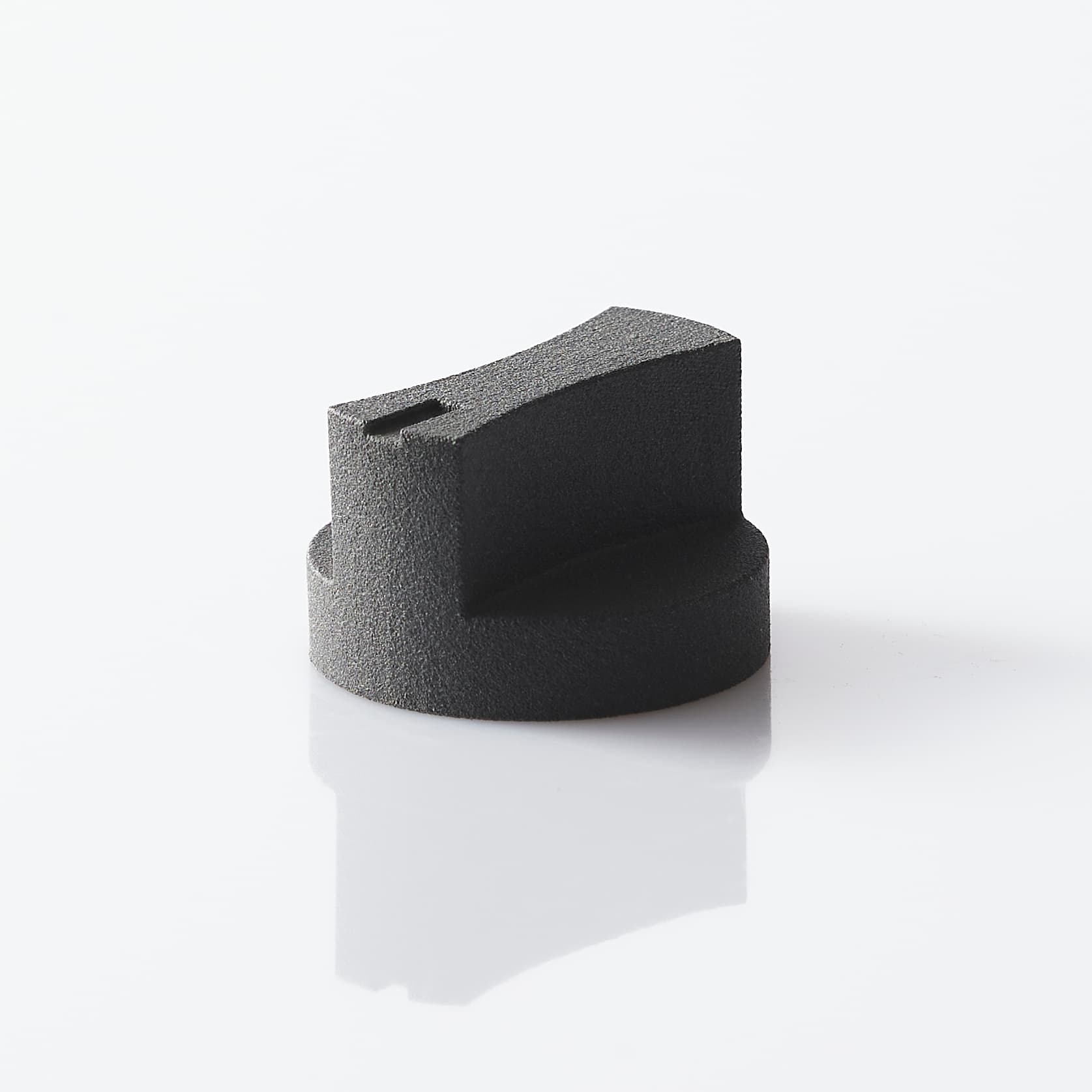
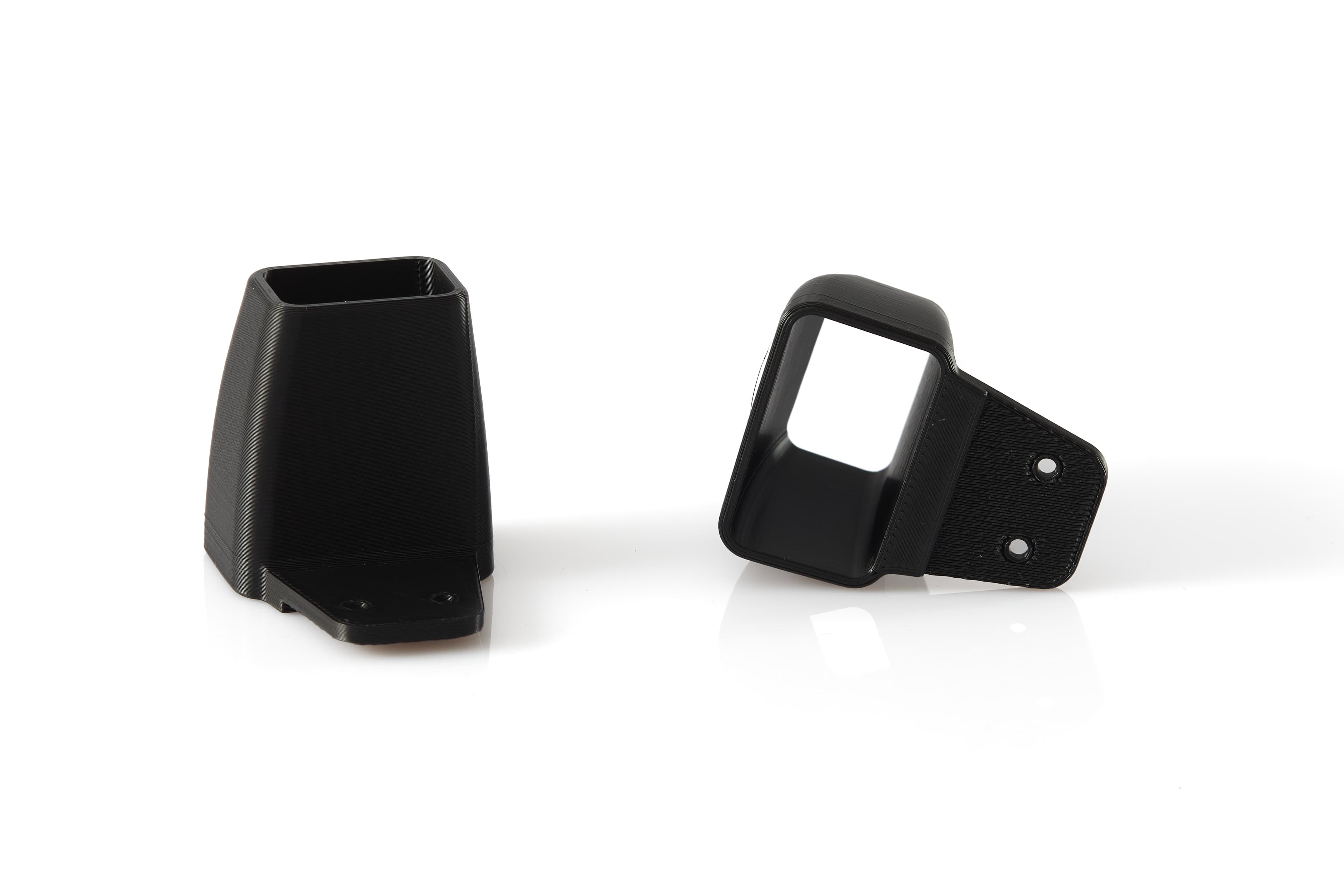
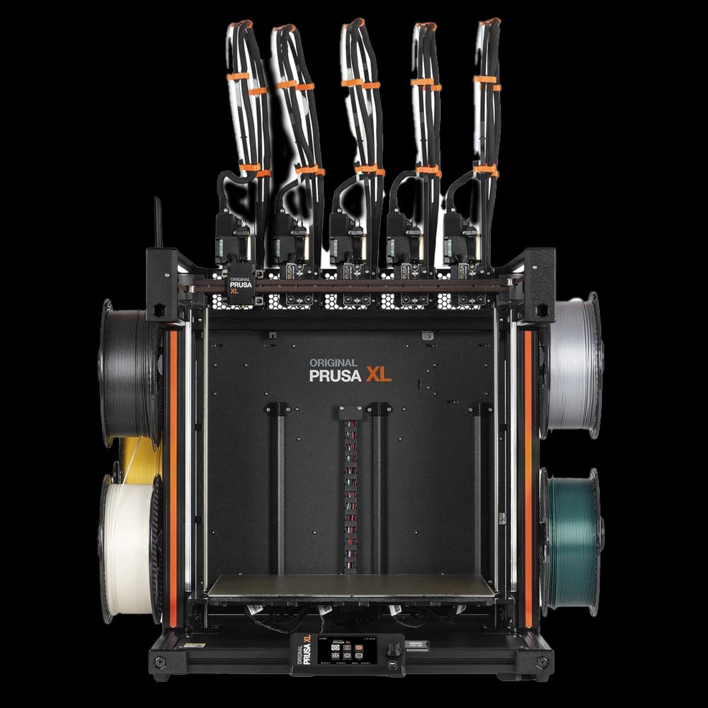
A 3D-printed component can be correctly dimensioned, withstand the expected heat and still not meet the flame requirement of the application. This guide to printable flame-retardant materials clarifies the decisive point: flame resistance does not depend only on the declared polymer, but on the combination of material, process, geometry, print orientation and test criterion.
For a technical office, the choice should not start from the question "which is the best flame-retardant filament?", but from a measurable requirement: which standard must be met, at what thickness, in what operating environment and on which real component? Only in this way can the prototype or small run go from the CAD file to a useful validation, without creating unverifiable expectations.
What "flame retardant" really means in 3D printing
In technical language, a flame-retardant material is formulated to limit ignition, slow flame propagation, reduce dripping or promote self-extinguishing within defined conditions. It does not mean that the material is non-combustible, nor that it retains its mechanical characteristics after exposure to a heat source or a flame.
This distinction matters because many datasheets report classifications obtained on printed or injection-moulded specimens, with specific thickness, orientation and conditioning. A final part with thinner walls, cavities, ribs or a different layer direction can behave differently. The flame figure is therefore a system figure, not a universal label applicable to every geometry.
In the United States, the UL 94 classification is among the most frequent references for electrical and electronic components. The HB, V-2, V-1 and V-0 classes describe different behaviours in standardised tests. In simplified terms, V-0 requires shorter afterflame times and does not allow flaming drips that ignite the cotton beneath; V-2 may allow them. The comparison, however, only has value when specimen thickness and process correspond to the application case.
For vehicle interiors FMVSS 302 may be required; in aerospace, requirements such as FAR 25.853 are common. Rail, medical, energy and industrial equipment sectors may call up further standards or proprietary protocols. There is therefore no single "fireproof" certification valid for every market.
Printable flame-retardant materials: start from the requirement
Before selecting a technology, gathering four pieces of information immediately reduces the risk of error: applicable standard, required class, minimum thickness of the part and environmental conditions. To these should be added mechanical stresses, continuous and peak temperature, exposure to humidity or chemical agents, electrical requirements and expected quantity.
A housing for an electrical panel, for example, does not require flame behaviour alone. It might require dielectric strength, dimensional stability, heat resistance, precision on mating features and surfaces suited to technical marking. An internal support for electronics might instead prioritise weight reduction, thin walls and a UL 94 classification declared at a thickness close to that of the design.
When the requirement concerns certification of the final product, two levels must be separated. The first is the material documentation: datasheet, batch, production process and test conditions. The second is the conformity of the final component, which may require tests on representative samples. The fact that a resin or filament is marketed as flame retardant does not automatically transfer the certification to the part produced.
Thickness and geometry are not details
Flame performance is often declared at one or more specific thicknesses. If the component includes a 0.8 mm wall, but the data available refers to 1.5 mm or 3 mm, equivalence cannot be assumed. Thin bridges, ventilation openings, ribs and heat-accumulation zones deserve a dedicated check.
Joint design also has an influence. Gaps and openings can favour the passage of flame or the entry of hot particles; metal inserts, wiring and gaskets introduce materials with different behaviours. For technical enclosures, the requirement must be read at assembly level and not only at the level of the printed shell.
Materials and technologies: advantages, limits, use cases
Additive technology determines isotropy, finish, precision, porosity and repeatability. For this reason, two materials of the same chemical family but produced with different processes are not directly interchangeable.
FDM: practicality and attention to anisotropy
In FDM, engineering polymers with flame-retardant additives are available, often based on ABS, PC, PC-ABS, PETG or polyamides formulated for electrical and industrial applications. The advantage is the availability of materials suited to medium-to-large components, functional tooling, covers and mounts, with controllable costs for prototypes and small runs.
The main compromise is the layered structure. Adhesion between layers depends on process parameters, material moisture, chamber temperature and geometry. This affects both mechanical strength and the part's response to heat and flame. Orienting the part merely to reduce supports may not be the best choice when loads, clips or thin walls subject to regulatory requirements are present.
FDM is appropriate when the selected material has adequate documentation and the design can respect the required thicknesses, radii and orientations. It is less suitable if the part must have very uniform aesthetic surfaces or tight tolerances in all directions without a finishing and inspection phase.
MSLA: precision, but rigorous validation
Flame-retardant resins for MSLA printing can offer high detail, clean surfaces and good precision on complex geometries. They are of interest for compact enclosures, connectors, interfaces, electronic components and prototypes that require a higher level of definition than many extrusion processes.
Post-curing is an integral part of the process. Washing, UV exposure, time, temperature and orientation can change mechanical and thermal properties. A resin treated outside the conditions specified by the manufacturer may not match the datasheet values. For functional components it is also necessary to check brittleness, long-term behaviour, moisture absorption and chemical compatibility.
The precision of MSLA does not replace the conformity check. If the part has to be qualified, the production cycle must be defined and repeatable: same resin, same parameters, same post-cure, same finish and batch traceability.
SLS: geometric freedom for functional parts
Selective laser sintering is valued for producing functional parts without supports, with internal geometries, complex mounts and small runs. However, the most common standard polyamides should not be considered flame retardant by default. Any flame requirement calls for the use of a specific formulation and documentation consistent with the SLS process.
The slightly porous surface can be an advantage or a limit depending on the use. Painting, sealing or dyeing can improve appearance and cleanability, but add a layer that must be assessed when a fire-behaviour requirement is present. An unqualified finish can alter the test result or introduce variability between batches.
How to design a more verifiable component
A part intended for flame testing must be designed with a production mindset, not only an aesthetic one. Consistent walls help control the process; adequate radii reduce stress concentrations; ribs and clips must be sized considering both the loads and the thickness declared in the material documentation.
For a project with strict requirements, it is useful to define a frozen configuration from the outset: material and colour, technology, orientation, relevant parameters, post-processing and markings. Changing the colour, adding a paint or switching supplier after the test may require a new assessment. Pigments and additives can also affect the effective formulation.
Laser marking is often useful for batch code, revision, part number and traceability. Before adopting it on a component with a flame-retardant requirement, the depth and position of the engraving must be checked: a marking that is too aggressive can locally thin a wall or create a critical point near a functional zone.
From CAD to validation sample
An effective flow begins with a clean STEP or STL file and an explicit statement of standard, class, critical thickness and conditions of use. The technical check should identify insufficient walls, unproducible details, tolerances incompatible with the process and areas that require a specific finish.
The next phase is not necessarily full production. To reduce time and cost, it is often worth making a first pilot batch with the same configuration planned for the final part. These samples serve to check assembly, deformation, dimensional stability and, when necessary, to support testing at a qualified laboratory.
Doppialinea manages this step with a single point of contact, from manufacturability checking to in-house printing and finishing. The operational advantage is not just receiving a quick quote: it is being able to discuss, before production, which constraints of the material and the process affect the real part.
The right choice is not the material with the most reassuring label, but the one that is documented and producible in the required configuration. When standard, geometry and process are defined before the first sample, 3D printing becomes a concrete tool for validating and producing technical components, not an uncontrolled shortcut.