A sensor mount that flexes, a jig that does not repeat positioning or a housing that prevents maintenance can slow a line more than an out-of-spec electronic component. This guide to industrial automation components starts from here: a part is right when it meets its real function, integrates without improvised adaptations and maintains consistent performance over time.
For technical departments, R&D teams and integrators, additive manufacturing is particularly useful when rapid iterations, customised geometries and limited batches are needed. It does not automatically replace processes such as CNC machining, sheet metal or moulding. But it reduces time and constraints in the phases where changing a component still has a sustainable cost.
Industrial automation components: start from the function
Before choosing a material or technology, define what the component has to do. The same bracket can be a simple spacer, a geometric reference for a camera or the link between an actuator and a structure. Loads, tolerances, finish requirements and the level of validation needed all change.
It is best to describe the function with measurable data: static and cyclic load, direction of forces, expected number of cycles, operating temperature, contact with oils or detergents, vibration, exposure to dust and accessibility for assembly and cleaning. For a component installed in the United States, compatibility with imperial interfaces, UNC or NPT threads and customer standards must also be checked. The CAD model must make these conditions explicit, not leave them to interpretation in the workshop.
A cable carrier, for example, is often underestimated. It must respect the cable's minimum bend radius, avoid sharp edges, withstand repeated movements and allow quick replacement. If it holds a harness on a robotic axis, mass, envelope and fixing carry more weight than for an element mounted on a fixed structure.
The most suitable families of components
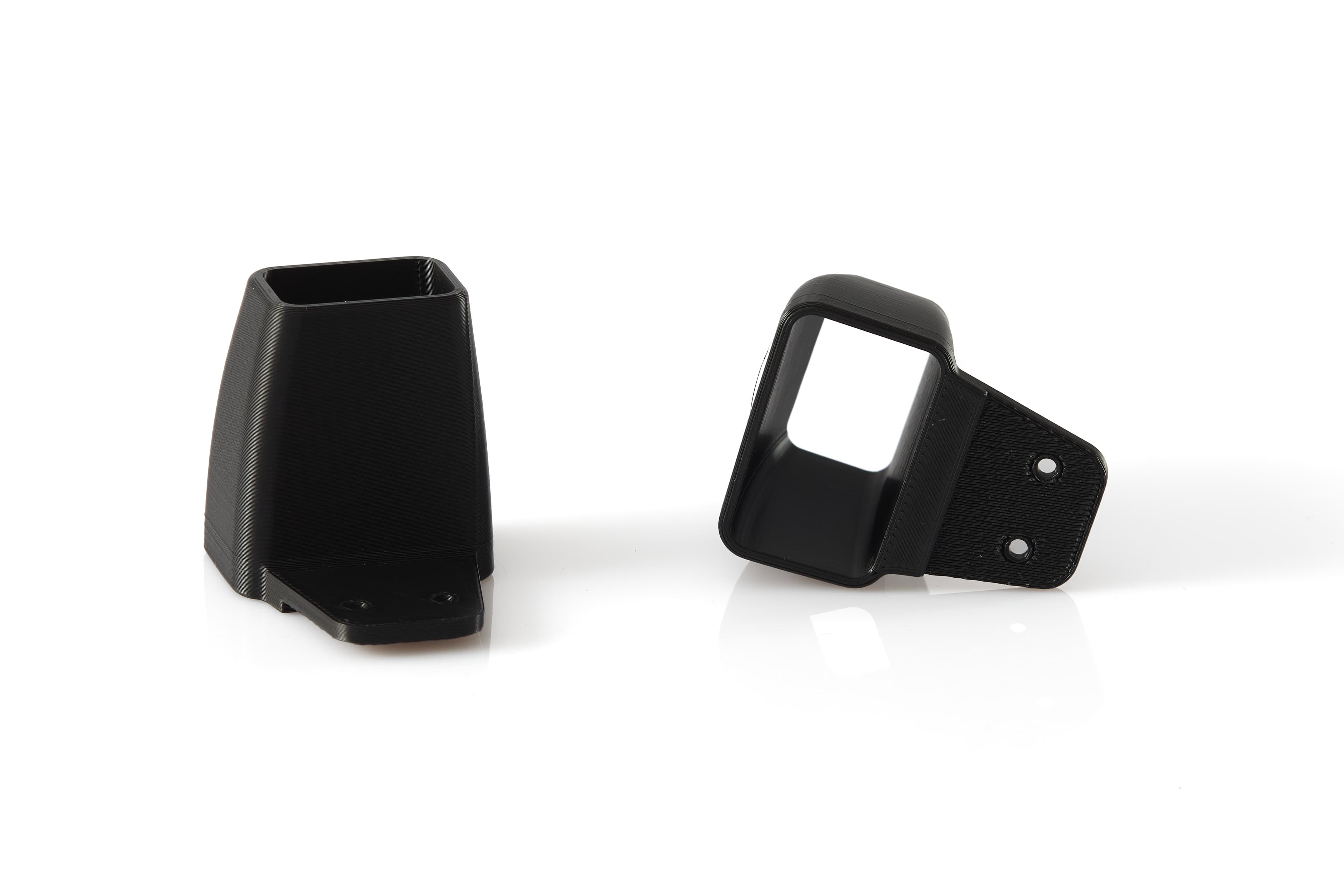
Recurring additive applications include brackets for sensors and cameras, HMI mounts, non-structural housings and guards, guides for cables and piping, assembly jigs, check fixtures, custom grippers, profile adapters and technical enclosures. These are parts where the specific geometry creates value: it eliminates assemblies of standard parts, shortens assembly or allows a machine to be adapted to a new format.
The case is different for primary safety elements, components subject to high pressures or parts whose failure could cause harm to people and plant. Here analysis, testing and compliance criteria proportionate to the risk are needed. 3D printing can be part of the project, but it should not be chosen solely for convenience or speed.
Material and technology: choose according to the duty
The material should not be selected from the datasheet alone. A property declared in the laboratory is not enough to predict the behaviour of a real geometry, oriented and post-processed for a specific technology.
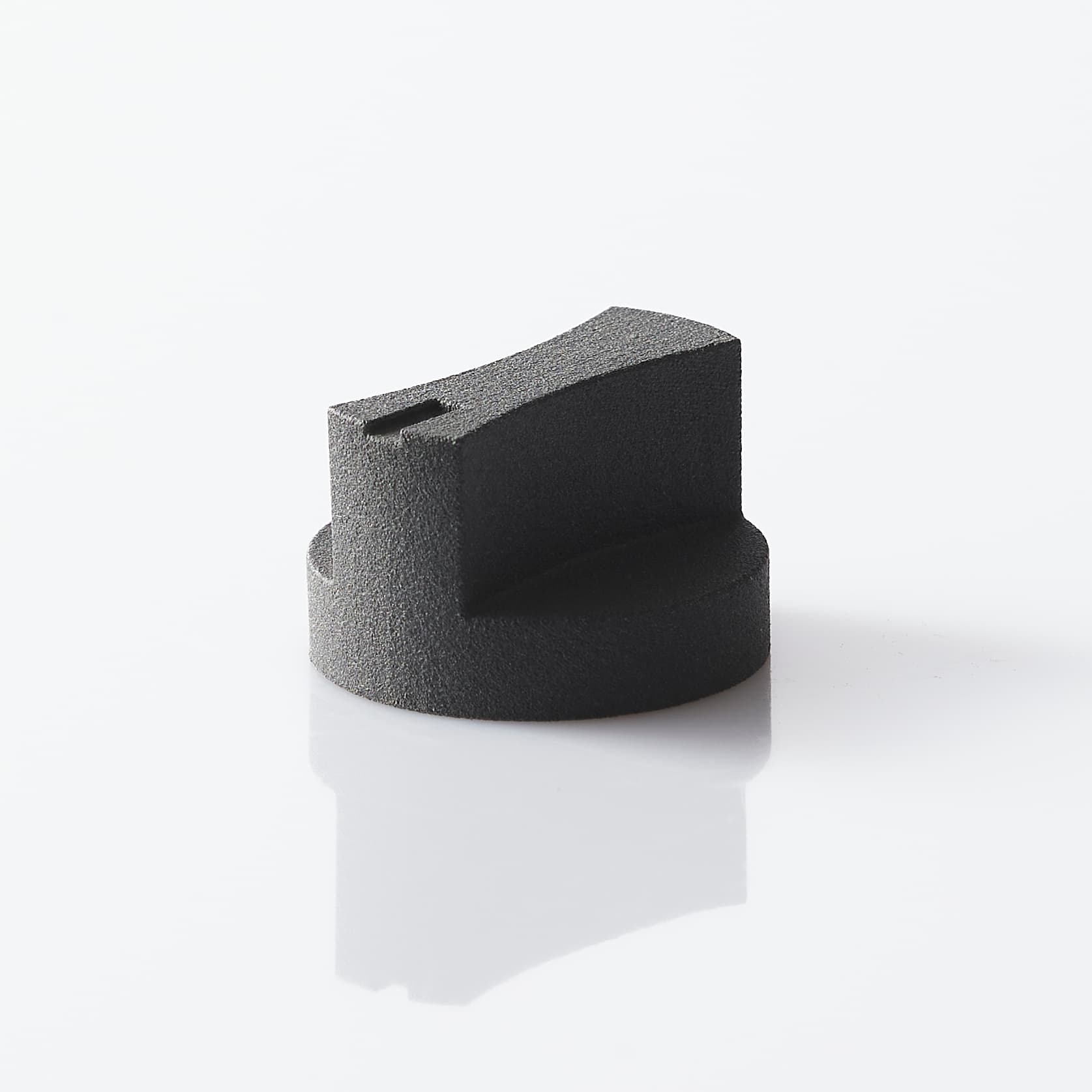
PA12 produced by SLS is a frequent choice for functional components, thanks to good mechanical strength, stability and geometric freedom. It is suited to brackets, shells, mounts and parts for light-to-medium-duty handling. The natural finish has a slightly porous surface: it can suit many industrial applications, while dyeing and post-processing may be useful for aesthetic needs, cleanability or visual identification.
TPU is appropriate when flexibility, shock absorption, surface protection or an elastic seal is needed. It is used in buffers, feet, guards, anti-abrasion guides and gripping components. The compromise is lower stiffness: it is not the material to choose for maintaining a dimensional reference under load.
MSLA resins allow fine details and accurate surfaces, useful for precision prototypes, small housings, masks and interference checks. The selection must, however, carefully consider brittleness, temperature and ageing. A very precise resin is not necessarily the best choice for a component exposed to impact and repeated cycles.
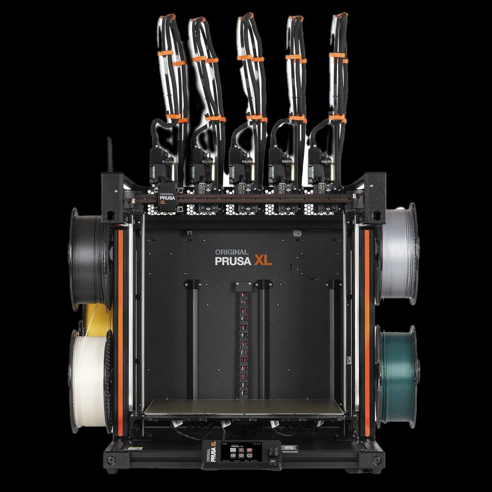
FDM can be effective for prototypes, jigs, tooling and larger parts, especially when the main requirement is to speed up geometric verification. Anisotropy between layers and surface quality must be assessed in the direction of the loads and in the mating seats.
Tolerances, interfaces and references: where repeatability is decided
Many components fail not because of the main body, but because of a hole, a bearing seat, a thread or a stop surface designed without considering the process. In industrial automation the critical dimension is not always the smallest one: it is the one that determines the relative positioning between sensor, actuator, tool and workpiece.
It is useful to distinguish functional dimensions from non-critical ones. The former require declared tolerances, reference surfaces and, if necessary, subsequent machining. A screw hole can be printed with a machining allowance and brought to size by reaming. A highly stressed thread may require metal inserts. For repeated fits, it is preferable to design dowel pins, clean stops and seats accessible to tools.
Tolerance should be defined on the assembly, not on the isolated single part. If a camera has to maintain a precise field of view, the chain includes the mount, profile, fasteners, any adapters and the assembly method. Requiring a tight tolerance across the whole geometry increases cost and complexity without necessarily solving the overall error.
Design for additive manufacturing, not just for printing
A printable file is not always a file that can be produced repeatably. Walls that are too thin, massive zones, cavities that cannot be evacuated, small threads and critical surfaces oriented without criteria can generate defects, unplanned post-processing time or variability between batches.
Design should consider from the start the minimum thickness consistent with the material, the radii at stress concentration points, access for removing powder or supports and the position of aesthetic or functional surfaces. In closed shells produced by SLS, for example, openings must be provided to empty out the unsintered powder. In MSLA parts, adequate drain and wash holes must be planned.
Print orientation is also a technical choice. It can affect strength, local accuracy, support marks and visual quality. It is one of the reasons why checking the file before production has real value: it prevents an apparently minor detail from compromising a batch or requiring urgent changes after assembly.
From validation to small batch
The first part should answer precise questions: does it fit into the assembly? Do the screws go in without forcing? Does the sensor hold its position after vibration? Can the operator reach the component? Without a test plan, the prototype risks becoming merely an aesthetic confirmation.
After the assembly test, it is useful to record the changes directly on the CAD and freeze a revision. Part code, revision, material, finish and inspection instructions must accompany the next order. This discipline is essential when a component moves from prototype to pre-series or is reordered for machines installed at different sites.
For small runs, the priority is not only unit cost. Material repeatability, technology availability, revision management and the ability to maintain the same level of finish all count. A single technical point of contact reduces handovers between file checking, production and post-processing. In this workflow, Doppialinea handles everything from CAD to finished part, with SLS, MSLA and FDM technologies, finishing and in-house production control.
Technical marking and component traceability
When the part goes into a machine or a retrofit kit, identification and revision are not administrative details. Laser engraving can carry part code, revision, serial number, assembly direction or customer identifier. The marking must be placed on a legible surface, not subject to critical wear and compatible with the material and finish.
Planning the marking area in the CAD avoids later interventions and makes maintenance more orderly. For components destined for several installations, consistent coding speeds up recognition of the spare part and limits installation errors.
The best component is not the one with the most complex geometry, but the one that arrives on the line, assembles first time and remains understandable months later to whoever has to replace it. Designing with this goal turns 3D printing from an urgent fix into a reliable method for evolving automation.