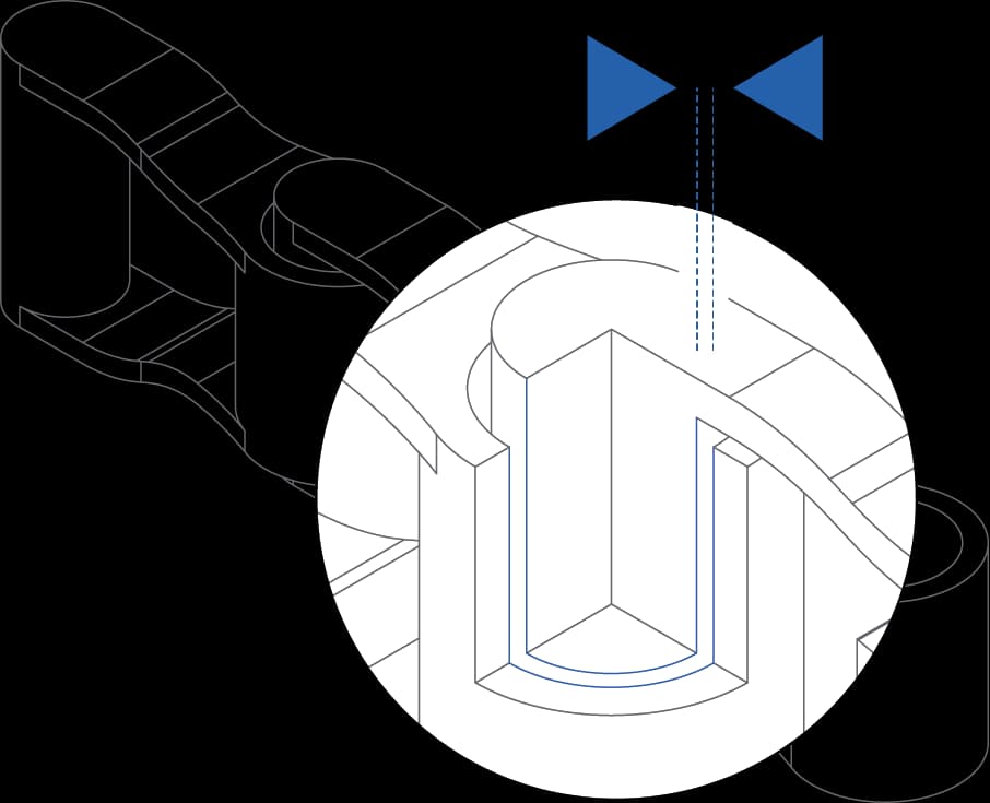
Chamfer external edges
A chamfer or small radius on external edges makes them less fragile and nicer to handle. In FDM, on the side resting on the build plate, prefer a 45° chamfer to a fillet.
For designers
Walls, holes, clearances and fillets for parts that are right first time.
The rules to keep in mind in CAD before sending us a file, for SLS, MSLA and FDM: practical values, technical drawings and the reasons behind every number.
At a glance
The most-used minimum values side by side. The sections below give the details and the drawing for each rule.
| Parameter | SLSSelective laser sintering | MSLAResin printing | FDMFilament printing |
|---|---|---|---|
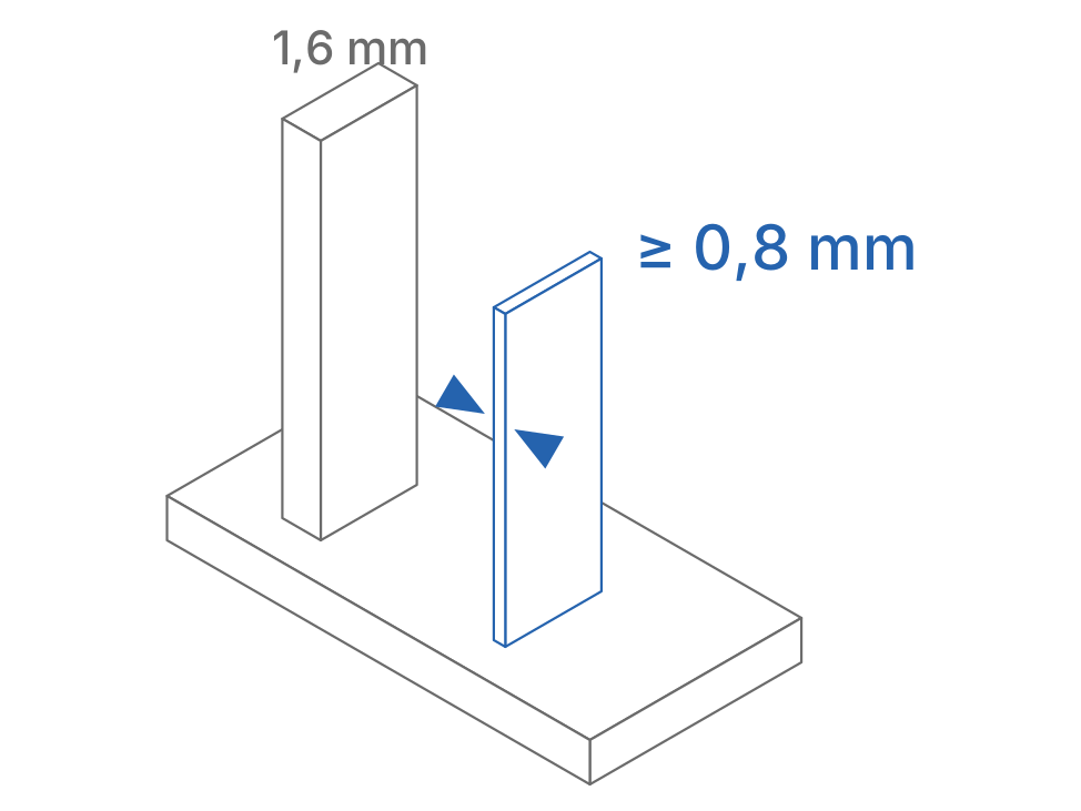
| Minimum wall | 0.6 mm | 0.4 mm (0.6 if self-supporting) | 0.8 mm (1.6 recommended) |
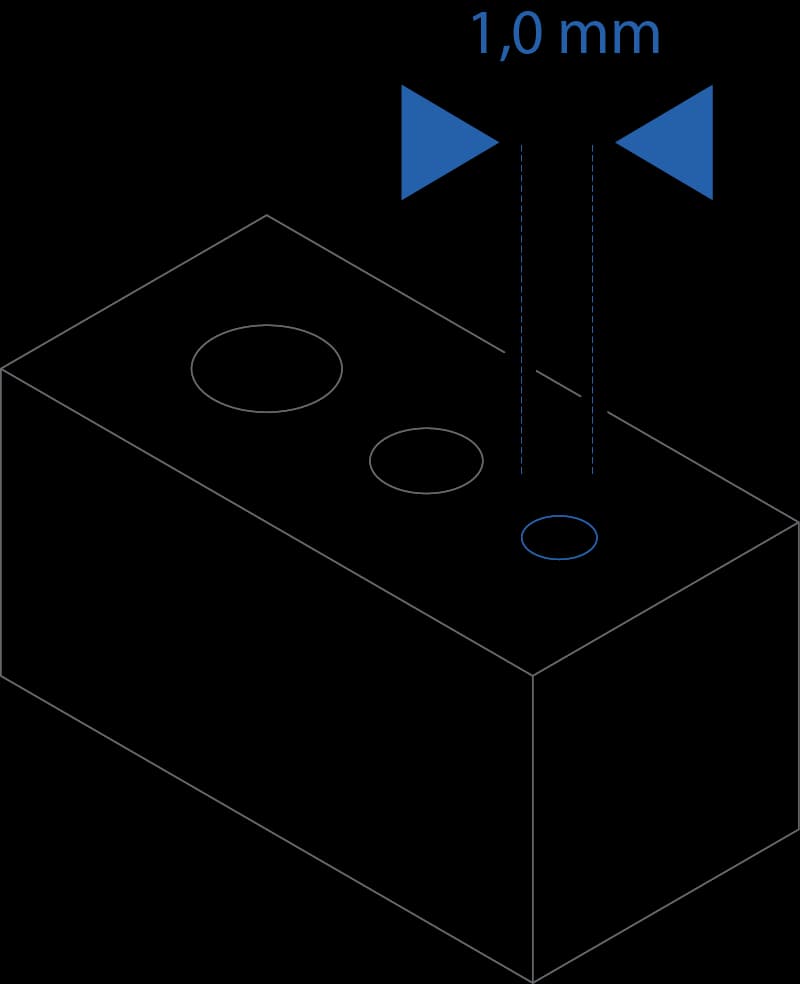
| Minimum hole | 1.0 mm | 0.5 mm | 2 mm |
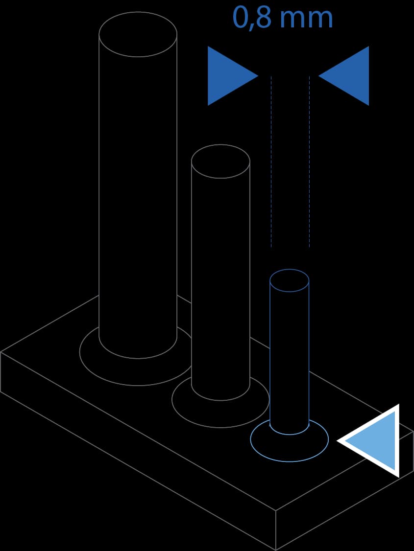
| Minimum pin | 0.8 mm | Assessed per part | 3 mm |
| Clearance for mating parts | 0.2–0.4 mm | 0.1–0.2 mm | 0.3 mm per side |
| Minimum embossed detail | 0.15 mm | 0.15 mm | 0.5 mm |
| Minimum engraved detail | 0.1 mm | 0.3 mm | 0.6 mm |
| Typical tolerance | ± 0.3 mm or ± 0.3% | ± 0.1–0.2 mm | ± 0.5 mm or ± 0.5% |
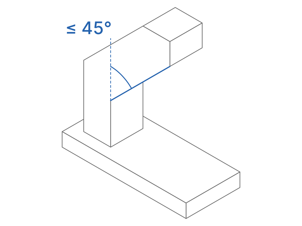
| Supports | Not needed | Always, leave small marks | Beyond 45° from vertical |
| Best for | Functional parts, snap fits, complex shapes | Fine detail, smooth surfaces, small parts | Jigs, large parts, engineering materials |
Valid for every technology
Before the minimum values, a few design choices make the difference on any printed part.
Sharp corner
All the stress concentrates in the corner: that is where the crack starts and the arm snaps off.
With a fillet
The radius spreads the stress over a wider area: the part flexes slightly and carries the same load. A 0.5–1 mm radius is a good default; where the part carries load, use the largest radius you can, roughly equal to the wall thickness.
A chamfer or small radius on external edges makes them less fragile and nicer to handle. In FDM, on the side resting on the build plate, prefer a 45° chamfer to a fillet.
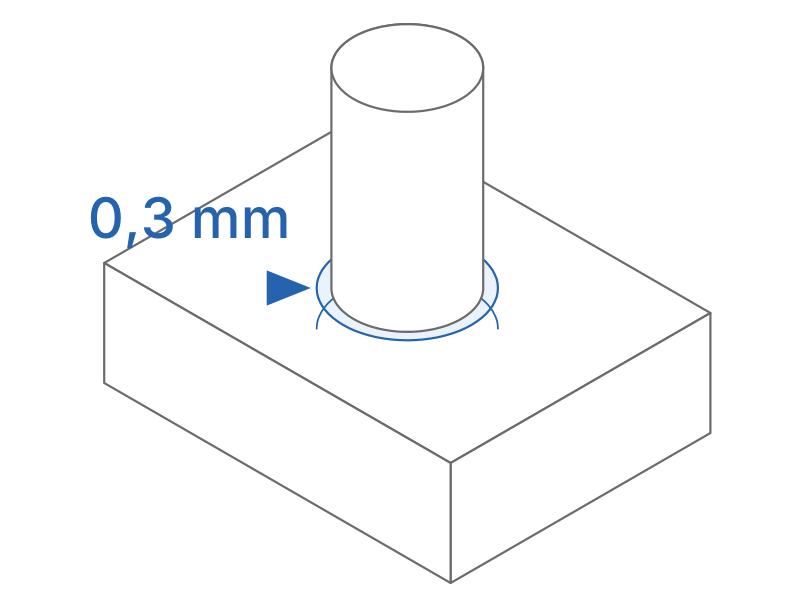
Clearance per side is half the difference between diameters. A 10 mm pin with 0.3 mm per side needs a 10.6 mm hole. Always state which one you mean.
Abrupt changes from thin to thick areas shrink differently, causing warping and stress. Blend thickness changes and hollow out solid areas.
To add stiffness, use ribs thinner than the wall they reinforce, with a small fillet at the root: several thin ribs are better than one thick one. They weigh less, cost less and warp less than a solid block.
For precision holes, bearing seats and datum faces, draw them slightly undersized and have them machined: post-print finishing gives the precision that printing alone cannot guarantee.
Whenever you can, send us the STEP as well as the STL. If you only send STL, export it at high resolution and in millimetres, checking the mesh is closed.
Selective laser sintering
Optimise the design of your components for selective laser sintering. Click each section to view the recommended parameters, technical images and design notes based on the printer manufacturer's guidelines.
≥ 0.8 mm
≥ 1.0 mm
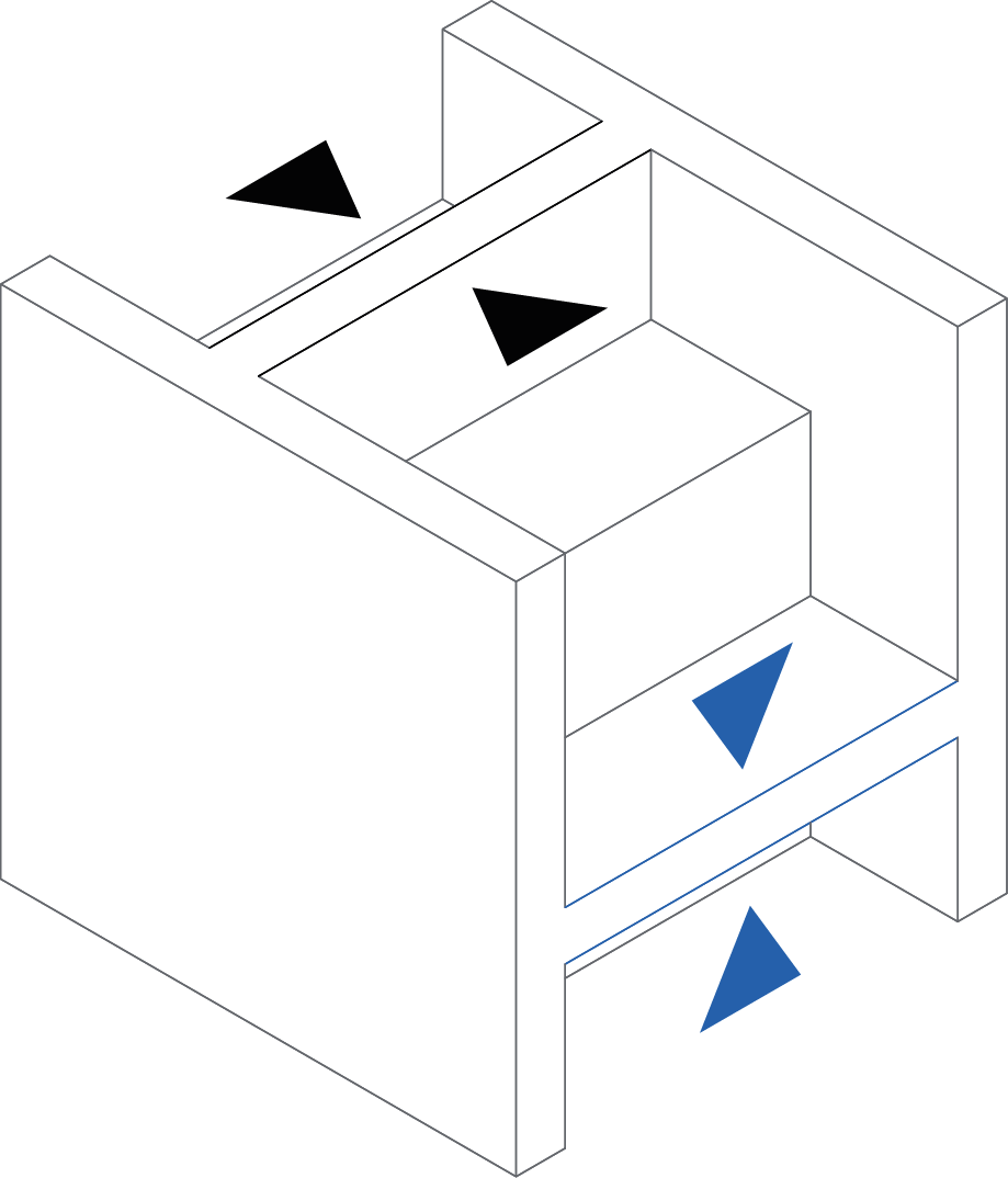
Vertical walls 0.6 mm / horizontal 0.3 mm

≥ 0.7 mm recommended
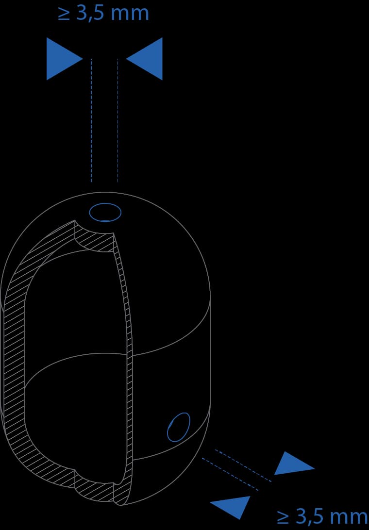
≥ 3.5 mm
A. Horizontal surfaces • B. Vertical surfaces
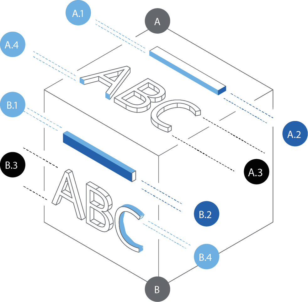
A. Horizontal surfaces • B. Vertical surfaces
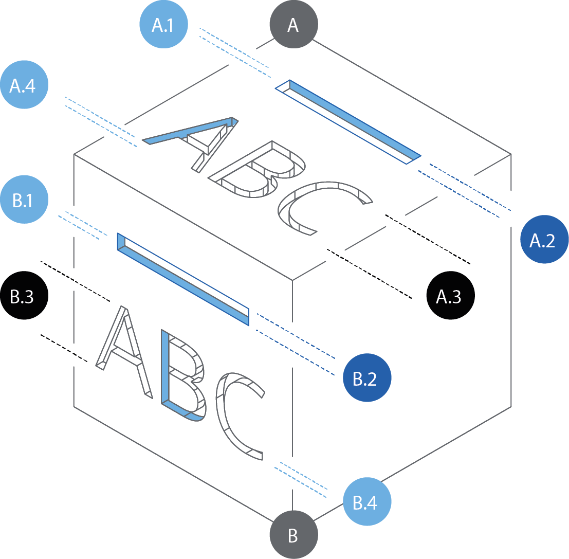
± 0.3 mm (standard)
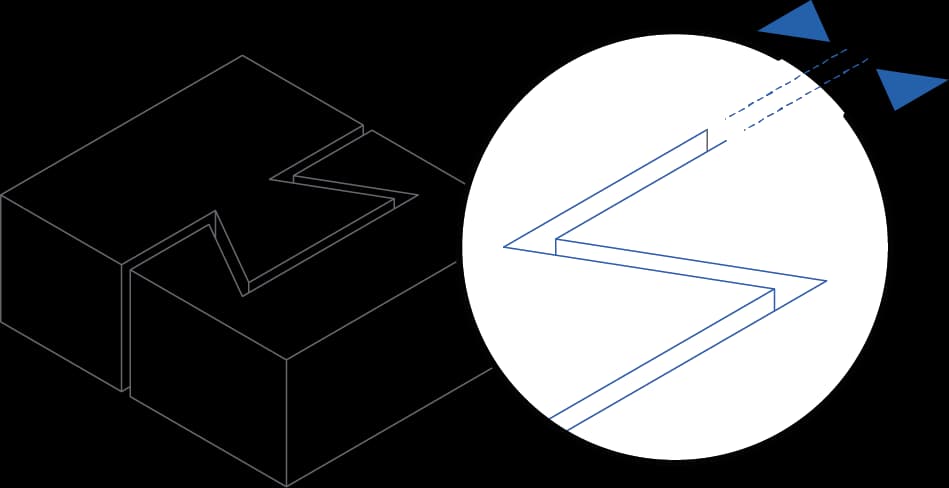
0.2 – 0.4 mm
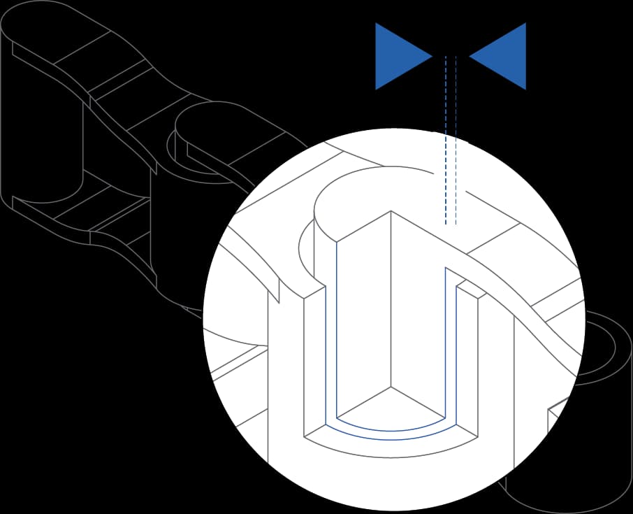
Resin printing
Optimise your models for resin printing with SLA/MSLA technology. Check the key parameters for smooth surfaces, high precision and professional results.
± 0.1 – 0.2 mm
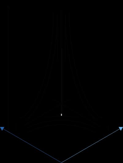
≥ 0.4 mm (self-supporting ≥ 0.6 mm)

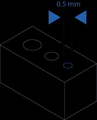
≥ 0.5 mm
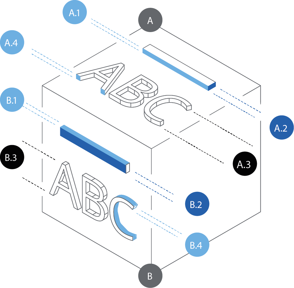
Minimum height: 0.15 mm • Text ≥ 3 mm
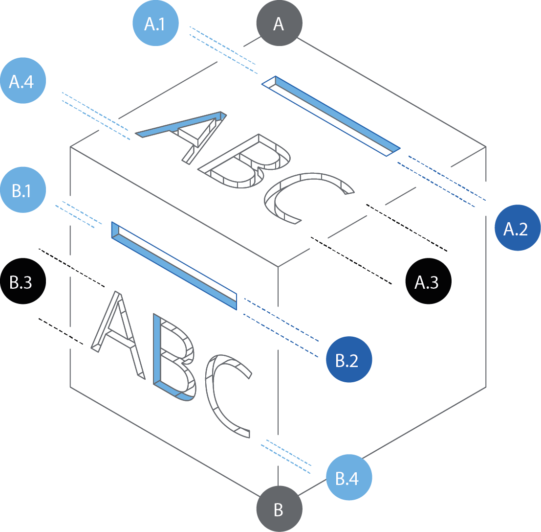
Minimum depth: 0.3 mm • Text ≥ 3 mm
0.1 – 0.2 mm
Filament printing
Optimise the design of your components for filament 3D printing. Click each section to see the recommended values, the technical drawing and the design notes. Values refer to a 0.4 mm nozzle and our standard settings (4 walls, 30% infill).
≤ 45° from vertical
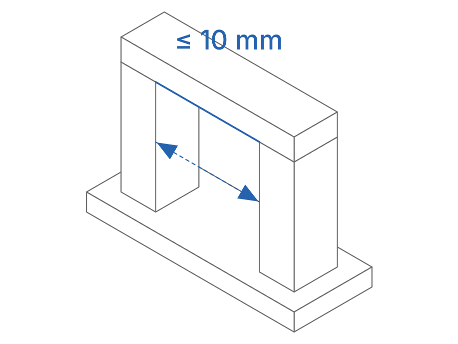
≤ 10 mm recommended
≥ 0.8 mm · 1.6 mm recommended
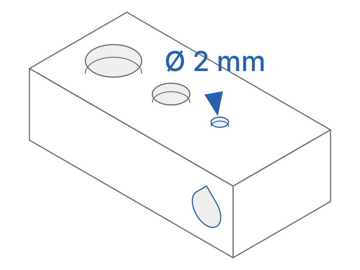
≥ 2 mm
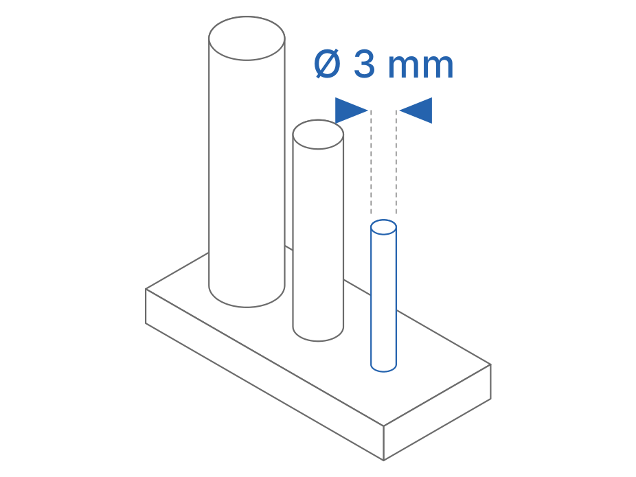
≥ 3 mm
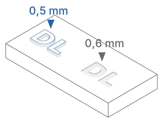
Embossed ≥ 0.5 mm · engraved ≥ 0.6 mm
0.3 mm per side
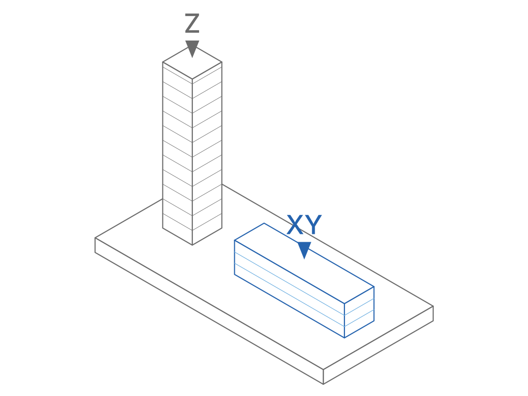
Z axis is the weakest
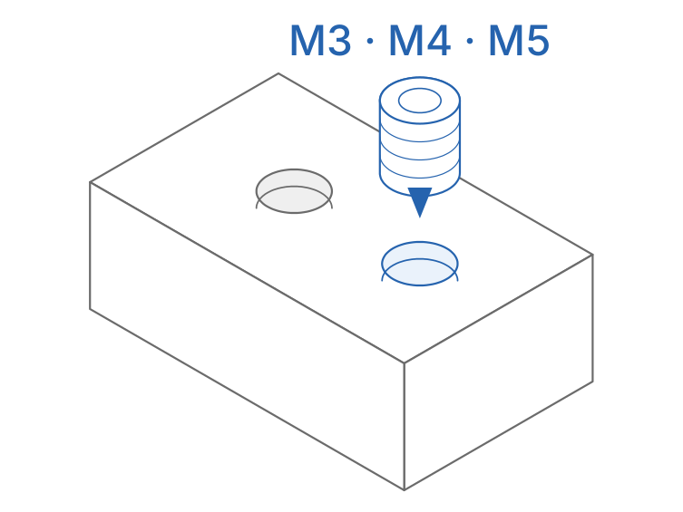
Heat-set inserts for M3–M5
New service
No 3D printer? Send us the drawing of the part you want to make in carbon fibre: we design the mould, print it and ship it to you. With your layup kit you make the part in fibre and resin.
Ask for a mould quoteSend us the drawing
The STEP file of the finished part, with the laminate thickness you want and the side that must come out glossy.
We design and print the mould
We add draft, radii, a trim edge and, if needed, locating pins. We print it with the moulding surface smooth and free of supports.
Layup with your kit
Release agent, fabric and resin, vacuum bag and cure. The part comes out of the mould ready to trim and finish.
Single-sided mould
One glossy face, the one against the mould; the other is formed by the vacuum bag. The simplest option for hand layup.
Two-part mould
Both faces smooth: the laminate is closed and pressed between the two halves, aligned by locating pins.
Master pattern
A model of the part from which you can make several moulds yourself, when you need more copies.
2–3° draft
A positive draft angle of 2–3° on the walls makes demoulding easier and extends the life of the mould.
Radii, no sharp corners
Fabric does not follow sharp corners and air bubbles form there. The radius is chosen according to the laminate thickness: smooth shapes work best.
Trim edge
The mould is larger than the part: excess material ends up on an edge and is trimmed afterwards, following the reference lines.
Smooth moulding surface
We orient the mould so supports never touch the face that forms the part, with thin layers for an already smooth surface.
Release agent everywhere
Wax and polyvinyl alcohol (PVA) over the whole surface: even a small uncovered area keeps the part stuck.
How many parts per mould
A 3D printed mould is meant for prototypes and small runs: roughly ten parts, depending on geometry, resin and cure temperature.
Room-temperature layup: the standard mould is fine. Oven cure or prepreg: tell us the temperature and we will choose a heat-resistant material.
Ask for a mould quoteSend us the file with a couple of lines on how the part works: our technical team will tell you what is worth changing before printing.
Note: the following guidelines are indicative only and may vary depending on the material, the part geometry and the print parameters used. For specific projects or advanced technical requirements, we recommend contacting the Doppialinea technical department for personalised advice.